HomeExperience
Later when Variable frequency drive (VFD) came out, then came the concerns about the various original standard motors' compatibility with VFDs with respect to bearing arcing, and motor winding temperature and voltage ratings, especially VFD drives without any load filtering. Motors for VFDs are also covered under NFPA 20, 9.5.1.4
An inverter duty motor can deal with the higher voltage spikes produced by VFDs also can run at very slow speeds without overheating. The general purpose motor don´t, it can overheat if it is running too slowly, so bearings and insulation will be damaged.
My understanding is that Variable Frequency Drive (VFD) controllers can vary voltage and amps, as they vary frequency, in order to get the required torque and power at lower speeds.
first convert RTD (a transducer) to a sensor, for which you can design a instrumentation amplifier using opamp, or use wheatstone bridge with RTD on test arm, balance the bridge by adjusting variable resistors on other arms & take the wheatstone o/p signal & connect is to an amplifier (preferably an opamp, so, that its, min & max range o/p current range become 4mA to 20mA) & you can connect this sensor signal to analog I/Os of variable frequency drive.
Replacing capacitor due to age should be done only in a repair shop that can load test the VFD drive after replacement. Remember for most spare drives have been on the shelf for over a year you need to reform the capacitors as part of the yearly maintenance. Also remember that if the system is not checked like the motor cable/connections, belts and couplings the variable frequency drive can still be damaged. Yearly preventive maintenance is always for the system not the VFD self in my opinion.
There might be some confusion about leading and lagging power factor. For an induction motor, positive current is defined as flowing into the positive terminal of the motor. Therefore, by definition, lagging power factor for a motor (or any load for that matter) is inductive (looks like an inductor). Leading power factor for a motor is capacitive (looks like a capacitor).
If your goal is to be able to verify correct repair of a VFD power section, then testing at full load is not important. You need to stress the IGBT's at peak current. Many people do this by using a motor with a high inertia flywheel (or pulley) and setting a relatively fast acceleration and deceleration time. For instance, use your 11kW motor, if your VFD under test is higher in power then you must set a faster acceleration time to properly stress the IGBT's. If your VFD under test is smaller in power, then you would need to set a longer acceleration time to properly stress the IGBTs. Remember, the goal is to stress them, not cause them to fail.
Can your VFD do "catch-on-the-fly"? The easiest thing to do is to couple an identically rated motor to the motor connected to your VFD. Start the second motor with a normal motor starter, ie soft starter, and then start your VFD in "catch-on-the-fly" mode at full rated speed. Slowly turn UP the VFD frequency reference ABOVE line frequency, monitoring the current draw, until you reach full-rated current. The motor being run from the starter will be regenerating power to the utility by operating above synchronous speed. If you try to run the VFD motor BELOW line frequency, it will regenerate power into the VFD and most probably cause it to trip due to high DC bus voltage.
In fact, the manufacturers of this particular band saw sells the induction motor / VFD drive as a servo axis. The customers don't know the difference but they just cannot cut straight and the saw bands don't last very long.
However, the manufacturer doesn't care very much. So one customer asked another band saw manufacturer to help. He replaced the induction motor and VFD with a real servo system and the saw works just perfect now.
Almost everything today including inexpensive VFDs power monitors etc. comes with standard, or optional, Ethernet and/or MODBUS. Getting "engineers" to specify the design requirements is a different story especially in the commercial BMS industry.
You can help to troubleshoot by implementing a good alarm/message system (I have seen many package units with only an alarm indicating a problem "PLC FAILURE") and asking for well documented applications (software and hardware, good tag naming, etc) and if you feel more comfortable by using a particular programming language (because it's used in other parts in your plant or you have staff able to understand it) go for it if reasonable
V/Hz was the original methodology developed by VFD manufacturers. One of the weaknesses in V/Hz is starting torque and lack of control. Vector type methodology was developed in the 80s to give better control at lower frequencies but could not go to 0 speed. Therefore a third methodology, Field Control, was developed that can give full torque at 0 speed.
Servo motor operation is affected by Standard VFD carrier frequency. Special Spindle drive is available from CNC drives manufacturers which does not affect servo operation.

Category
AC Motor Control
Featured
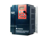 This low voltage (single phase 220V, three phase 380V) variable frequency drive manufactured by Gozuk has compact design and integrated advanced technology ...
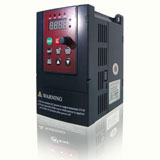
 Special magnetic flux vector control VFDs
Power range: single phase 1.5kW to 2.2kW, 3 phase 0.75kW to 400kW
Integrated RS485, Modbus-RTU communication protocol
32 ...
Active Front End (AFE) variable frequency drive has some harmonic filtering at the input to the VFD that is "programmable" on the fly. Basically, a microprocessor ...
An inverter duty motor can deal with the higher voltage spikes produced by VFDs also can run at very slow speeds without overheating. The general purpose motor ...
Multiple motors operation is quite common application. There are many applications like textile, printing etc where multi motor operation is very common. I ...
In summary, when using a VFD there are many benefits and cost saving possibilities for pumping applications in the irrigation sector. It is important to look ...
Special magnetic flux vector control VFDs
Power range: single phase 1.5kW to 2.2kW, 3 phase 0.75kW to 400kW
Integrated RS485, Modbus-RTU communication protocol
32 ...
Active Front End (AFE) variable frequency drive has some harmonic filtering at the input to the VFD that is "programmable" on the fly. Basically, a microprocessor ...
An inverter duty motor can deal with the higher voltage spikes produced by VFDs also can run at very slow speeds without overheating. The general purpose motor ...
Multiple motors operation is quite common application. There are many applications like textile, printing etc where multi motor operation is very common. I ...
In summary, when using a VFD there are many benefits and cost saving possibilities for pumping applications in the irrigation sector. It is important to look ...
Recent
Increase the speed of a motor by VFD
VFD in Crane and Hoist Applications
VFD for Fire Pump Motors
Is it VFD the best solution to control pump?
3HP VFD, single phase to three phase VFD
Insulated bearings for electric machines
Control ABB VFD through RTD 250ohm directly on water temp
Variable frequency drive Preventive Maintenance
Large VFD trips with power supply by transformer
Induction motor power factor
Understanding VFD basics
Does the motor lifetime depend on the starts number & frequency?