VFD in pulp & paper machines
Overall
The system is with the control method of PLC combined with VFDs. Each drive point is with buttons for site speed regulation. The block diagram of the system is shown as Figure 1.
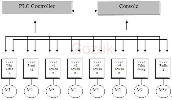
Figure 1. System Block Diagram
The VFD is Gozuk GK3000 series. The whole system can provide the following functions:
Control of Speed Chain
According to the paper machine and production process flow, papers on the paper machine prolong longitudinally at wet end due to traction action; papers continue to prolong longitudinally when the dry end starts; after the water content of papers reduces, such prolonging reduces; and when papers enter paper calendaring and reeling machines, they prolong once again due to traction. Therefore, in the whole production line of the paper machine, the speed of each individual is different so as to keep tension for paper web. Meantime, the speed of each individual of the paper machine shall be adjustable so as to avoid loose of paper web or breaking caused by tensioning, with speed regulating range of each individual: 10-15%.
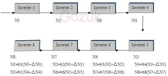
Figure 2. Calculation and Control of Speed Chain
After transmitting the speed command of drive points to VFDs, visit location register to determine the node number of the sub-register. If the node number is not "0", conduct corresponding processing for this node until the whole chain is processed completely. After that, check the node number of brother registers and process another chain. Thus, it is only required to initialize the location register to form any branch speed chain.
As shown in Figure 1, the first individual point of the paper machine is regarded as the main node of the speed chain, namely its speed determines the working speed of the whole paper machine, so regulation of its setting speed is to regulate the speed of the complete paper machine. For example, in PLC, if speed regulation signal is detected, then change speed unit value; the speed at "1" point is just the operating speed setting value of the first VFD, which is sent to the first VFD for execution and to the second for calculation. The speed value of the first individual is multiplied with the ratio of the second individual (b1×a) is the setting value of the second VFD. If the speed of the second individual cannot meet operating requirements, this means the ratio of the second individual is not suitable. You can regulate the ratio of the second individual (b1) to meet required operating requirements. This regulation is equivalent to be with a high-accuracy gear box in PLC so that any stepless speed regulation is available.
During normal production, if the ratio is suitable and it is required for paper tensioning or releasing for some reasons, press appropriate buttons of this individual, and then PLC will add one positive or negative offset to appropriate speed chain to realize such paper tensioning or releasing functions. In the figure, the "2" point includes speed values for commands for speed regulating and paper tensioning and releasing etc., which are send to the second VFD for execution and to the next step for calculation at the same time. And so forth, the control system of speed chains is formed.
Reeling Tension Control
Tension control shall be used for the paper reeling part of the paper machine. If the paper machine has high production requirements for papers, the tension close-loop control can be added in the calendaring part. The tension control is with two methods available for selection: 1) the close-loop control with direct tension detection; 2) the close-loop control with indirect tension calculation and testing. The VFD for tension control shall be with GK3000 series VFD.
1. Close-loop Control with Direct Tension Detection
The GK3000 VFD module has two levels: one level for universal functional modules such as PID control, multi-step frequency, and automatic energy-saving operation etc.; another level for special functional modules such as location control, textile application, and constant-pressure water supply application etc. The GK3000 VFD also has rich programmable modules with complete functions and flexible programming, including: 1 two multi-function comparators that can define faults by themselves; 2 two logical units that can carry out calculations such as "and", "or", and "xor"; 3 two timers that can realize various time-delay functions; 4 one counter that can preset values and can save data after power off; 5 four arithmetical units that can add, subtract, multiply, and divide and can calculate absolute values.
Besides, GK 3000 variable frequency drive also has built-in process PID with complete functions, which is essential in close-loop tension control. Details are shown below:

The input and feedback channels of PID have many categories for selection, and the feedback signals also can be set as many types of calculation results that are calculated from analog values. The PID can be preset and has two sets of parameters that can be switched over during operation. Users can freely carry out programming for resources of GK3000 VFD, not only able to use its programmable functional modules to coordinate with special functional modules, but also able to use these two types of modules to realize special functions for various industries. The programmable functional modules of the GK3000 VFD are like a group of jigsaw puzzles which can form numberless ideal patterns in users' hand. This makes it be able to provide solutions platform and integration solutions for various industry requirements and thus it is very valuable for reduction of system cost and increasing of system reliability.
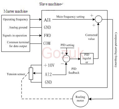
The control structure of the system is shown as below: the operating frequency of the master machine (four cylinders or calendaring variable frequency drive) is used as the main setting frequency for slave machines (calendaring machine or reeling VFD); the output of tension control PID regulator performs corrections for the main setting frequency so that there is no difference between the feedback tension and setting tension. The output signal from the tension sensor is used as PID feedback, and the PID setting is set as ideal tension value with numbers. The operating signals of the master machine are used as start/stop commands for slave machines.
The system diagram is shown as below:
2. Close-loop Control with Indirect Tension Calculation and Detection
Based on the operating frequency of the master machine (four cylinders or calendaring VFD) which represents the speed of the production line and on the real-time roll diameter of reeling papers, calculate the main setting frequency of corresponding slave machine (reeling machine), which shall be used as feedforward; while, the PID regulator shall be used to control PID tension output of papers; and the setting frequency shall be subject to continuous corrections, and the corrected frequency shall be used as setting frequency of the reeling motor. This compound control method integrating feedforward and feedback has a high control accuracy, and many variable frequency drives special for tension control use this method. The GK3000 VFD can realize this control through programming by programmable control modules, with convenient use and flexible methods. The control block diagram of the system is shown as below:
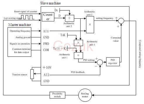
Fig. Tension Control System of GK3000 VFD in Paper Reeling Machine
Note: in this diagram, D0 refers to the percentage of initial roll diameter, and the final roll diameter is regarded as 100%.
T0 refers to initial tension value, and the maximum tension of tension sensor is regarded as 100%.
K refers to tension taper parameter and shall be set by users within range of 0-100%.
The analog operating frequency (representing production line speed) of master machine shall be input through AI1.
Lap scoring signal shall be input through "Counter" with photo-electric switch.
The PID feedback value shall be input through AI2 from tension sensor.
The reset signal for roll diameter is added to preset an initial value as count value.
The following will explain this combined method by two parts.
Calculation of setting frequency for reeling machine
Users need know three values: initial roll diameter, final roll diameter, and paper thickness. Based on the three values, calculate the following values required for parameter setting:
1. D0 (percentage of initial roll diameter)=Initial roll diameter/final roll diameter.
2. Setting value of counter =Final roll diameter/(paper thickness×2)
3. Preset value of counter =Initial roll diameter/(paper thickness×2)
Take the following example for explanation:
If the final roll diameter of papers is 1000mm, initial roll diameter of 100mm, and film thickness of 0.05mm, then:
D0=100/1000=10%;
Setting value of counter =1000/(0.05×2)=20000;
Preset value of counter = 100/(0.05×2)=2000.
At this moment, the count value of counter (with setting count value as 100%) is equivalent to an output signal of a roll-diameter sensor, i.e. real-time roll-diameter value D (with final roll diameter as 100%). The power-off memory of the counter realizes the power-off memory function for roll diameter, and its reset realizes the function that the roll diameter is reset to initial roll diameter.
Considering the frequency of master machine as F0, frequency of slave machine as F, and current roll diameter as D (with final roll diameter as 100%), we know:
F0×D0=F×D;
It is able to calculate that: F=F0×(D0/D);
First, calculate the value of D0/D through arithmetic unit 3; and then calculate the value of F0 (i.e. AI1) through arithmetic unit 2, which is multiplied to the output of arithmetic unit 3 so as to get the value of F. At this moment, the result of arithmetic unit 2 is just the main setting frequency of the reeling machine, so the frequency setting channel for reeling machine is set as the setting of arithmetic unit 2. By this, the setting of main setting frequency of reeling machine is complete.
Setting Calculation of PID
With the method of close-loop tension control, the setting value of PID shall be set as tension value required by users. The result of arithmetic unit 1 is just the real-time tension value required by users, and the setting channel of PID is set as the setting of arithmetic unit 1. By this, the setting of setting channel for PID is complete.
Arriving here, the design of tension control solution is complete. Besides, some external wiring and parameter setting required for control shall be done, including: the in-service signal of master machine is used as start signal of slave machine so that slave machine operates following with master machine; regulate relevant PID parameters based on actual situations to achieve best control effects.
The automatic control of each individual of the paper machine utilizes joint control of PLC and variable speed drives, which is the development trend for design and transformation of paper-making drives. Its practicability, reliability, economy and intelligent can provide a high cost performance for users. After transformation, equipment has a higher automation degree, production process is more reliable and stable, and the energy saving of low-speed operation of VFDs can bring significant economic benefits for users.
In control system, the speed sync of each individual is completed by PLC and VFDs together. PLC is responsible for each individual and speed chain calculation. The VFDs carry out speed instructions from PLC and complete fine speed regulation (including cascade and complete-machine fine speed regulation) by themselves.
The speed chain of VFDs is with binary tree data structure to carry out data transmission functions. First, perform mathematical abstract for all drive points to determine a number for each drive point in the speed chain, and the number shall be consistent with the internal address of the variable frequency drive. Then, determine the upper and lower as well as left or right numbers for each node point according to the binary tree data structure. That is to say, the location of any drive point in the speed chain shall be decided by three data, and then fill the location in the location register.
The system is with the control method of PLC combined with VFDs. Each drive point is with buttons for site speed regulation. The block diagram of the system is shown as Figure 1.

Figure 1. System Block Diagram
The VFD is Gozuk GK3000 series. The whole system can provide the following functions:
- The drive points of each individual shall be able to start and stop separately and shall be adjustable for their speeds;
- The complete machine shall be sync speed increasing and decreasing;
- Speed regulation of one individual can result in a sync speed regulation at this individual and its subsequent individuals;
- The speed shall be automatically recovered as original operating speed after paper tensioning;
- The maximum design speed shall be adjustable according to production requirements;
- The system shall be with emergency stop function.
Control of Speed Chain
According to the paper machine and production process flow, papers on the paper machine prolong longitudinally at wet end due to traction action; papers continue to prolong longitudinally when the dry end starts; after the water content of papers reduces, such prolonging reduces; and when papers enter paper calendaring and reeling machines, they prolong once again due to traction. Therefore, in the whole production line of the paper machine, the speed of each individual is different so as to keep tension for paper web. Meantime, the speed of each individual of the paper machine shall be adjustable so as to avoid loose of paper web or breaking caused by tensioning, with speed regulating range of each individual: 10-15%.

Figure 2. Calculation and Control of Speed Chain
After transmitting the speed command of drive points to VFDs, visit location register to determine the node number of the sub-register. If the node number is not "0", conduct corresponding processing for this node until the whole chain is processed completely. After that, check the node number of brother registers and process another chain. Thus, it is only required to initialize the location register to form any branch speed chain.
As shown in Figure 1, the first individual point of the paper machine is regarded as the main node of the speed chain, namely its speed determines the working speed of the whole paper machine, so regulation of its setting speed is to regulate the speed of the complete paper machine. For example, in PLC, if speed regulation signal is detected, then change speed unit value; the speed at "1" point is just the operating speed setting value of the first VFD, which is sent to the first VFD for execution and to the second for calculation. The speed value of the first individual is multiplied with the ratio of the second individual (b1×a) is the setting value of the second VFD. If the speed of the second individual cannot meet operating requirements, this means the ratio of the second individual is not suitable. You can regulate the ratio of the second individual (b1) to meet required operating requirements. This regulation is equivalent to be with a high-accuracy gear box in PLC so that any stepless speed regulation is available.
During normal production, if the ratio is suitable and it is required for paper tensioning or releasing for some reasons, press appropriate buttons of this individual, and then PLC will add one positive or negative offset to appropriate speed chain to realize such paper tensioning or releasing functions. In the figure, the "2" point includes speed values for commands for speed regulating and paper tensioning and releasing etc., which are send to the second VFD for execution and to the next step for calculation at the same time. And so forth, the control system of speed chains is formed.
Reeling Tension Control
Tension control shall be used for the paper reeling part of the paper machine. If the paper machine has high production requirements for papers, the tension close-loop control can be added in the calendaring part. The tension control is with two methods available for selection: 1) the close-loop control with direct tension detection; 2) the close-loop control with indirect tension calculation and testing. The VFD for tension control shall be with GK3000 series VFD.
1. Close-loop Control with Direct Tension Detection
The GK3000 VFD module has two levels: one level for universal functional modules such as PID control, multi-step frequency, and automatic energy-saving operation etc.; another level for special functional modules such as location control, textile application, and constant-pressure water supply application etc. The GK3000 VFD also has rich programmable modules with complete functions and flexible programming, including: 1 two multi-function comparators that can define faults by themselves; 2 two logical units that can carry out calculations such as "and", "or", and "xor"; 3 two timers that can realize various time-delay functions; 4 one counter that can preset values and can save data after power off; 5 four arithmetical units that can add, subtract, multiply, and divide and can calculate absolute values.
Besides, GK 3000 variable frequency drive also has built-in process PID with complete functions, which is essential in close-loop tension control. Details are shown below:

The input and feedback channels of PID have many categories for selection, and the feedback signals also can be set as many types of calculation results that are calculated from analog values. The PID can be preset and has two sets of parameters that can be switched over during operation. Users can freely carry out programming for resources of GK3000 VFD, not only able to use its programmable functional modules to coordinate with special functional modules, but also able to use these two types of modules to realize special functions for various industries. The programmable functional modules of the GK3000 VFD are like a group of jigsaw puzzles which can form numberless ideal patterns in users' hand. This makes it be able to provide solutions platform and integration solutions for various industry requirements and thus it is very valuable for reduction of system cost and increasing of system reliability.
The control structure of the system is shown as below: the operating frequency of the master machine (four cylinders or calendaring variable frequency drive) is used as the main setting frequency for slave machines (calendaring machine or reeling VFD); the output of tension control PID regulator performs corrections for the main setting frequency so that there is no difference between the feedback tension and setting tension. The output signal from the tension sensor is used as PID feedback, and the PID setting is set as ideal tension value with numbers. The operating signals of the master machine are used as start/stop commands for slave machines.
The system diagram is shown as below:

2. Close-loop Control with Indirect Tension Calculation and Detection
Based on the operating frequency of the master machine (four cylinders or calendaring VFD) which represents the speed of the production line and on the real-time roll diameter of reeling papers, calculate the main setting frequency of corresponding slave machine (reeling machine), which shall be used as feedforward; while, the PID regulator shall be used to control PID tension output of papers; and the setting frequency shall be subject to continuous corrections, and the corrected frequency shall be used as setting frequency of the reeling motor. This compound control method integrating feedforward and feedback has a high control accuracy, and many variable frequency drives special for tension control use this method. The GK3000 VFD can realize this control through programming by programmable control modules, with convenient use and flexible methods. The control block diagram of the system is shown as below:

Fig. Tension Control System of GK3000 VFD in Paper Reeling Machine
Note: in this diagram, D0 refers to the percentage of initial roll diameter, and the final roll diameter is regarded as 100%.
T0 refers to initial tension value, and the maximum tension of tension sensor is regarded as 100%.
K refers to tension taper parameter and shall be set by users within range of 0-100%.
The analog operating frequency (representing production line speed) of master machine shall be input through AI1.
Lap scoring signal shall be input through "Counter" with photo-electric switch.
The PID feedback value shall be input through AI2 from tension sensor.
The reset signal for roll diameter is added to preset an initial value as count value.
The following will explain this combined method by two parts.
Calculation of setting frequency for reeling machine
Users need know three values: initial roll diameter, final roll diameter, and paper thickness. Based on the three values, calculate the following values required for parameter setting:
1. D0 (percentage of initial roll diameter)=Initial roll diameter/final roll diameter.
2. Setting value of counter =Final roll diameter/(paper thickness×2)
3. Preset value of counter =Initial roll diameter/(paper thickness×2)
Take the following example for explanation:
If the final roll diameter of papers is 1000mm, initial roll diameter of 100mm, and film thickness of 0.05mm, then:
D0=100/1000=10%;
Setting value of counter =1000/(0.05×2)=20000;
Preset value of counter = 100/(0.05×2)=2000.
At this moment, the count value of counter (with setting count value as 100%) is equivalent to an output signal of a roll-diameter sensor, i.e. real-time roll-diameter value D (with final roll diameter as 100%). The power-off memory of the counter realizes the power-off memory function for roll diameter, and its reset realizes the function that the roll diameter is reset to initial roll diameter.
Considering the frequency of master machine as F0, frequency of slave machine as F, and current roll diameter as D (with final roll diameter as 100%), we know:
F0×D0=F×D;
It is able to calculate that: F=F0×(D0/D);
First, calculate the value of D0/D through arithmetic unit 3; and then calculate the value of F0 (i.e. AI1) through arithmetic unit 2, which is multiplied to the output of arithmetic unit 3 so as to get the value of F. At this moment, the result of arithmetic unit 2 is just the main setting frequency of the reeling machine, so the frequency setting channel for reeling machine is set as the setting of arithmetic unit 2. By this, the setting of main setting frequency of reeling machine is complete.
Setting Calculation of PID
With the method of close-loop tension control, the setting value of PID shall be set as tension value required by users. The result of arithmetic unit 1 is just the real-time tension value required by users, and the setting channel of PID is set as the setting of arithmetic unit 1. By this, the setting of setting channel for PID is complete.
Arriving here, the design of tension control solution is complete. Besides, some external wiring and parameter setting required for control shall be done, including: the in-service signal of master machine is used as start signal of slave machine so that slave machine operates following with master machine; regulate relevant PID parameters based on actual situations to achieve best control effects.
The automatic control of each individual of the paper machine utilizes joint control of PLC and variable speed drives, which is the development trend for design and transformation of paper-making drives. Its practicability, reliability, economy and intelligent can provide a high cost performance for users. After transformation, equipment has a higher automation degree, production process is more reliable and stable, and the energy saving of low-speed operation of VFDs can bring significant economic benefits for users.
In control system, the speed sync of each individual is completed by PLC and VFDs together. PLC is responsible for each individual and speed chain calculation. The VFDs carry out speed instructions from PLC and complete fine speed regulation (including cascade and complete-machine fine speed regulation) by themselves.
The speed chain of VFDs is with binary tree data structure to carry out data transmission functions. First, perform mathematical abstract for all drive points to determine a number for each drive point in the speed chain, and the number shall be consistent with the internal address of the variable frequency drive. Then, determine the upper and lower as well as left or right numbers for each node point according to the binary tree data structure. That is to say, the location of any drive point in the speed chain shall be decided by three data, and then fill the location in the location register.


