VFD for Fans & Pumps
I. Benefits of VFDs in Fans & Pumps applications
Most fans and water pumps are selected according to its full loads working status, but in practice they are not working at the full load state in most of the time. So to control flow & air volume of the pumps & fans, it needs a wind deflector, reflux valve or start/stop timer usually, and the large power ac motors are very difficult in start/stop frequently as the electric impact is in a high level, during this time, it's absolutely will cause electric energy wasted and high current impact during start/stop of the ac motor.
To solve this kind of problem, the most scientific way is to adopt a variable frequency drive to control the fans and water pumps. When the AC motor operates at 80% of its rated rotation speed, in theory, the power consumption is the cube of 80% of its rated power, i.e. 51.2%. Generally, it can almost save 40% power consumption for the manufacturer when deduct the impact of mechanical loss and ac motor copper and iron loss. Plus, it can improve energy-efficient when the fan & pump adopt closed-loop constant-pressure control which can be achieved easily. Due to the VFD drive can realize soft start and soft stop for the ac motors, it can avoid voltage surge during the motor's start period to decrease the failure rate and increase its service life, and reduce the power system's capacity requirements and reactive power loss.
II. Energy Conservation Analysis
Through the fluid mechanics' basic principles, we know the fans and pumps are belong to square torque loads, the rotation speed n, flow Q, pressure H and shaft power P relation: Q∝n, H∝n2, P∝n3, i.e., the flow is in proportion to its rotation speed, the pressure is in proportion to the square of its rotation speed, and the shaft power is in proportion to the cube of its rotation speed.
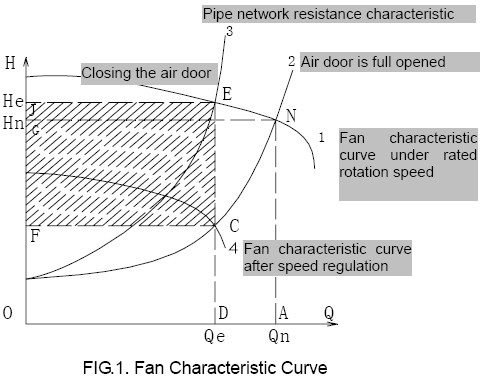
We now take the fan as an instance of the principle in energy conservation. As show in following fig, when the fan in its rated rotation speed, the air volume and air pressure change as curve 1, which intersects with the pipe network resistance curve 2 at the rated working condition point N when the air door is full opened; the air volume of the fan is Qn and the pressure is Hn. Normally, the working condition point is moved to point E by closing the regulation air door and increasing the resistance in ventilation pipe network. At this moment, the air volume is decreased to Qe and the generated pressure head is He. If the air volume is regulated by reducing the rotation speed of the fan, the fan will operate as curve 4, and re-generate required air volume Qe, it will intersect with the pipe network resistance curve 2 at the working condition point C when the air door is full opened.
According to the similar principles between fan and water pump, the air volume, rotation speed and power accordance with the following formula:

According to similar principles, when the rotation speed of the fan reduce to n2 from n1, the shaft power of the fan N2 will be reduced to N1 multiply (n1/n2)3; the shaded area in the FIG - the area covered by JECF represents the saved electric quantity by reducing rotation speed compared with closing the air door to regulate the same amount of air volume. Both theory and actual measurement prove that it will cause waste of electric energy by manual increasing ventilation resistance (closing the valve) to regulate the air volume, which is unacceptable.
If variable frequency technology is adopted to change the rotation speed of pumps and fans to control other process control parameters on the field such as pressure, temperature and water level, the comparison results mentioned above can also be obtained by drawing the relation curve in accordance with the system control characteristics. In other words, the method to adopt VFD to change the rotation speed of ac motor is more energy and cost efficient than by using valve and damper, and the operating condition of the equipment is also significantly improved.
III. Variable Frequency Reform Solution:
1. Main Circuit Diagram:
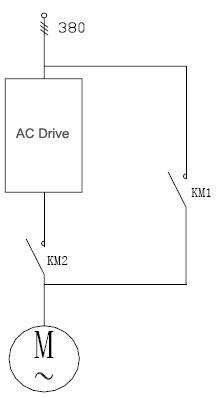
As shown in the above FIG, keep the original system but add the variable frequency drive part, All motors in the system are driven by corresponding VFDs, and when the VFD failed, the system can working in power frequency as the original control system to ensure continuous production in the factory.
2. Control Circuit
A. Manual regulate (open-loop regulation) system, adjust output frequency of the VFD in manual control mode to change the rotation speed of the fan & pump to regulate air volume & water volume. It's same as original method of regulating the air door (gate valve).
B. Automatic regulate (closed-loop regulation) system:
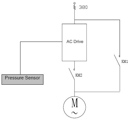
As shown in above FIG., the automatic control system adopts closed-loop regulation which is consisted of the VFD's built-in PID function with external pressure sensor or pressure gage. The sensor detects air pressure or water pressure in real time and transforms it into 4-20mA current signal (or 0-10V voltage signal), and sends it to the PID regulator, and through internal calculation of the variable speed drive, automatic regulate the frequency of the VFD to stabilize the air volume or water pressure at the set value.
3. Main features of vector control VFD in Fan and Water Pump application
The VFD is a product special designed for load with square torque like in fan and water pump applications, cost effective and reliable, it's an ideal choice for your energy saving system.
IV. System characteristics after reform
1) Realize AC motor's soft start/stop by adopting VFD control, to increase the equipment's service life and avoid impact on the power system.
2) Control the AC motor's rotation speed by the variable speed drive, remove the damper adjustment to decrease failure rate of the application, and increase electricity saving significantly.
3) The ac motor operates below rated rotation speed, to decrease impact of noises to the environment.
4) Do not affect original power facilities & environment during installation to allow continuous production.
5) Enhance overload, overvoltage, overcurrent, undervoltage and voltage phase lack protection functions, and audible and visual alarm function;
6) Due to keep the original system wiring and make the system have two working modes in normal power frequency & variable frequency power, the whole system operate in a more reliable situation.
Most fans and water pumps are selected according to its full loads working status, but in practice they are not working at the full load state in most of the time. So to control flow & air volume of the pumps & fans, it needs a wind deflector, reflux valve or start/stop timer usually, and the large power ac motors are very difficult in start/stop frequently as the electric impact is in a high level, during this time, it's absolutely will cause electric energy wasted and high current impact during start/stop of the ac motor.
To solve this kind of problem, the most scientific way is to adopt a variable frequency drive to control the fans and water pumps. When the AC motor operates at 80% of its rated rotation speed, in theory, the power consumption is the cube of 80% of its rated power, i.e. 51.2%. Generally, it can almost save 40% power consumption for the manufacturer when deduct the impact of mechanical loss and ac motor copper and iron loss. Plus, it can improve energy-efficient when the fan & pump adopt closed-loop constant-pressure control which can be achieved easily. Due to the VFD drive can realize soft start and soft stop for the ac motors, it can avoid voltage surge during the motor's start period to decrease the failure rate and increase its service life, and reduce the power system's capacity requirements and reactive power loss.
II. Energy Conservation Analysis
Through the fluid mechanics' basic principles, we know the fans and pumps are belong to square torque loads, the rotation speed n, flow Q, pressure H and shaft power P relation: Q∝n, H∝n2, P∝n3, i.e., the flow is in proportion to its rotation speed, the pressure is in proportion to the square of its rotation speed, and the shaft power is in proportion to the cube of its rotation speed.
We now take the fan as an instance of the principle in energy conservation. As show in following fig, when the fan in its rated rotation speed, the air volume and air pressure change as curve 1, which intersects with the pipe network resistance curve 2 at the rated working condition point N when the air door is full opened; the air volume of the fan is Qn and the pressure is Hn. Normally, the working condition point is moved to point E by closing the regulation air door and increasing the resistance in ventilation pipe network. At this moment, the air volume is decreased to Qe and the generated pressure head is He. If the air volume is regulated by reducing the rotation speed of the fan, the fan will operate as curve 4, and re-generate required air volume Qe, it will intersect with the pipe network resistance curve 2 at the working condition point C when the air door is full opened.

According to the similar principles between fan and water pump, the air volume, rotation speed and power accordance with the following formula:

According to similar principles, when the rotation speed of the fan reduce to n2 from n1, the shaft power of the fan N2 will be reduced to N1 multiply (n1/n2)3; the shaded area in the FIG - the area covered by JECF represents the saved electric quantity by reducing rotation speed compared with closing the air door to regulate the same amount of air volume. Both theory and actual measurement prove that it will cause waste of electric energy by manual increasing ventilation resistance (closing the valve) to regulate the air volume, which is unacceptable.
If variable frequency technology is adopted to change the rotation speed of pumps and fans to control other process control parameters on the field such as pressure, temperature and water level, the comparison results mentioned above can also be obtained by drawing the relation curve in accordance with the system control characteristics. In other words, the method to adopt VFD to change the rotation speed of ac motor is more energy and cost efficient than by using valve and damper, and the operating condition of the equipment is also significantly improved.
III. Variable Frequency Reform Solution:
1. Main Circuit Diagram:

As shown in the above FIG, keep the original system but add the variable frequency drive part, All motors in the system are driven by corresponding VFDs, and when the VFD failed, the system can working in power frequency as the original control system to ensure continuous production in the factory.
2. Control Circuit
A. Manual regulate (open-loop regulation) system, adjust output frequency of the VFD in manual control mode to change the rotation speed of the fan & pump to regulate air volume & water volume. It's same as original method of regulating the air door (gate valve).
B. Automatic regulate (closed-loop regulation) system:

As shown in above FIG., the automatic control system adopts closed-loop regulation which is consisted of the VFD's built-in PID function with external pressure sensor or pressure gage. The sensor detects air pressure or water pressure in real time and transforms it into 4-20mA current signal (or 0-10V voltage signal), and sends it to the PID regulator, and through internal calculation of the variable speed drive, automatic regulate the frequency of the VFD to stabilize the air volume or water pressure at the set value.
3. Main features of vector control VFD in Fan and Water Pump application
The VFD is a product special designed for load with square torque like in fan and water pump applications, cost effective and reliable, it's an ideal choice for your energy saving system.
- Wide range operation voltage, fluctuation range in 304 - 456V AC
- Special rotation speed tracking technology with no impact
- Several V/F curves in setting
- Multi-function input/output terminals with Multi-path definable function
- Re-start function in instant power off
- Built-in RS 485, support MODBUS-RTU communication protocol
- Stable start, suitable for high-inertia load's speed regulation
- Easy to realize closed-loop automatic operation with advanced built-in PID algorithm
IV. System characteristics after reform
1) Realize AC motor's soft start/stop by adopting VFD control, to increase the equipment's service life and avoid impact on the power system.
2) Control the AC motor's rotation speed by the variable speed drive, remove the damper adjustment to decrease failure rate of the application, and increase electricity saving significantly.
3) The ac motor operates below rated rotation speed, to decrease impact of noises to the environment.
4) Do not affect original power facilities & environment during installation to allow continuous production.
5) Enhance overload, overvoltage, overcurrent, undervoltage and voltage phase lack protection functions, and audible and visual alarm function;
6) Due to keep the original system wiring and make the system have two working modes in normal power frequency & variable frequency power, the whole system operate in a more reliable situation.


