HomeInstallation
The output terminals of the VFD provide a place to connect the three motor leads. These terminals are identified as U, V, and W. The labels R, S, and T for the input voltage and U, V, W for the output terminals are worldwide standards. Some VFDs made in the U.S. before 1990 may still be identified as L1, L2, and L3 for input terminals and T1, T2, and T3 for output terminals where the motor is connected.
The variable frequency drive sizing of 7.5hp with a 5hp motor is due to debating requirements when running the drive at high switching frequencies along with the starting torque requirements of the application. DBR need to be sized to match the braking IGBT within the VFD as far as a minimum resistance is concerned. And the resistor needs to of sufficient kW's to take into to account the duty cycle of the braking.
From aspects of installation you need to choose a well shielded cable segregating from HV cables additionally if it's an incremental encoder the configuration of bipolar is a good noise-immunized, which means you need 4 wires A/A-,B/B- at least from the encoder. If it's extreme circumstance you can choose a fibre as media.
Of course installing a reactor /dv/dt filter to the output of a VFD will reduce common noise and a shielded power cable is highly recommended to use.

Category
AC Motor Control
Featured
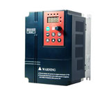 This low voltage (single phase 220V, three phase 380V) variable frequency drive manufactured by Gozuk has compact design and integrated advanced technology ...
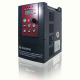
 Special magnetic flux vector control VFDs
Power range: single phase 1.5kW to 2.2kW, 3 phase 0.75kW to 400kW
Integrated RS485, Modbus-RTU communication protocol
32 ...
Active Front End (AFE) variable frequency drive has some harmonic filtering at the input to the VFD that is "programmable" on the fly. Basically, a microprocessor ...
An inverter duty motor can deal with the higher voltage spikes produced by VFDs also can run at very slow speeds without overheating. The general purpose motor ...
Multiple motors operation is quite common application. There are many applications like textile, printing etc where multi motor operation is very common. I ...
In summary, when using a VFD there are many benefits and cost saving possibilities for pumping applications in the irrigation sector. It is important to look ...
Special magnetic flux vector control VFDs
Power range: single phase 1.5kW to 2.2kW, 3 phase 0.75kW to 400kW
Integrated RS485, Modbus-RTU communication protocol
32 ...
Active Front End (AFE) variable frequency drive has some harmonic filtering at the input to the VFD that is "programmable" on the fly. Basically, a microprocessor ...
An inverter duty motor can deal with the higher voltage spikes produced by VFDs also can run at very slow speeds without overheating. The general purpose motor ...
Multiple motors operation is quite common application. There are many applications like textile, printing etc where multi motor operation is very common. I ...
In summary, when using a VFD there are many benefits and cost saving possibilities for pumping applications in the irrigation sector. It is important to look ...
Recent
Increase the speed of a motor by VFD
VFD in Crane and Hoist Applications
VFD for Fire Pump Motors
Is it VFD the best solution to control pump?
3HP VFD, single phase to three phase VFD
Insulated bearings for electric machines
Control ABB VFD through RTD 250ohm directly on water temp
Variable frequency drive Preventive Maintenance
Large VFD trips with power supply by transformer
Induction motor power factor
Understanding VFD basics
Does the motor lifetime depend on the starts number & frequency?